Exo-Skeleton Arm
Covid-19 Boredom Relief
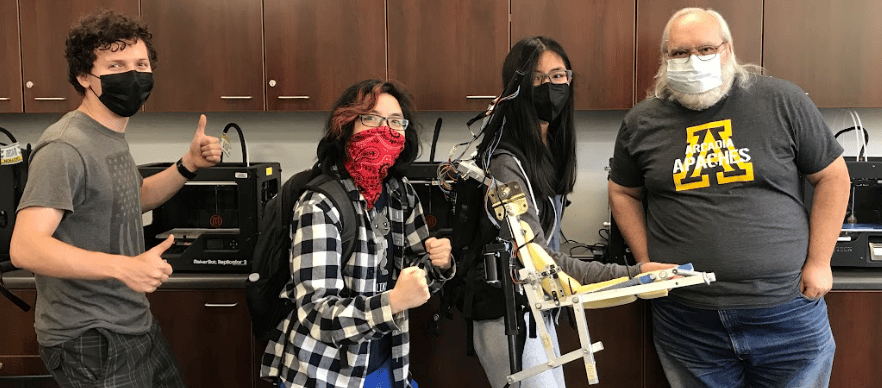

This was a project I did with a couple of friends from my high school robotics team. Originally, we needed to make a presentation on a specific component of our FRC robot, in our case, it was a linear actuator, but we wanted to be extra, so we decided to build an exoskeleton arm. Yes, a linear actuator is technically not ideal for this application but mechanical arms and pneumatics were taken by other groups. Also, this page was formatted primarily for desktop experiences so the mobile format may be scuffed.
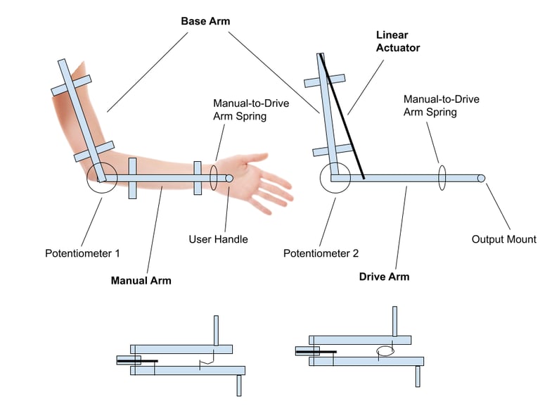

Rough Diagram made in Google Drawings
Technically we didn't need to build anything for this assignment, but this was during the COVID-19 lockdown and FRC season got canceled. Since we were starved of building robots for a little more than a year, we decided to make something for fun before we all had to graduate and leave. It just so happened to be related to the final assignment so we could make the the school pay for it.


Originally, we had no idea how to implement a linear actuator to work in the arm. While we knew it could handle the load, the problem was balancing the speed of the actuator, the load capacity, the price, and the shipping time as we had a two-week deadline. The trade-off of having linear actuators is usually the speed v.s. the torque of the motor spinning the lead screw and by extension the force it could exert. We also didn't want the stoke length to be too long or it would be awkward to have it attached to an arm.
Below are some of the linear actuators we considered
We started off with a very broad idea of what we wanted the arm to look like. The exo-arm consists of a base arm attached to the user's upper arm via straps at the bicep, a manual arm attached to the user's lower arm via straps at the wrist, and the drive arm where the linear actuator is attached. Both the manual and drive arms would pivot off the elbow joint. The drive arm would match the manual arm via the linear actuator and theoretically, bear most of the load that the manual arm normally would've.
We knew we wanted the movement of the linear actuator to be dictated by the angle the user's arm was in, so we implemented potentiometers at the elbow joint. We also added a spring to keep the drive arm attached to the manual arm.
Exo-Arm Design
Materials
We went to a metal supermarket near us to pick out a suitable alloy of aluminum for the arm and started prototyping. We ultimately decided on aluminum because it's lightweight, has a fantastic strength-to-weight ratio, and was relatively cheap. We ended up choosing 6061-T52 alloy cause it has a higher tensile, yield, and fatigue strength compared to the other alloys they had like 6063. It was also easier to machine. We chose square tubes as it was easier to drill and line out holes compared to cylindrical tubes at this scale.
The length of the base, manual, and drive were determined by averaging out the lengths of all of our arms, this way any three of us in the group could use it when prototyping and testing.
Below is a video of the bare skeleton of the exo-arm without the linear actuator, because at this point of the build process, it hadn't arrived yet.


Aleqxus with a safety remainder at the metal supermarket
In the video, you will notice that we mounted the arm to the frame of a hiking backpack. This is how the user wears the exo-arm and this frame acts as a support for the arm as it distributes the weight of the load.
And yes, we did use a door hinge for the shoulder joint because the rest of the build was made from scraps we had either lying around the workshop or in the depths of the robotics team storage shed.
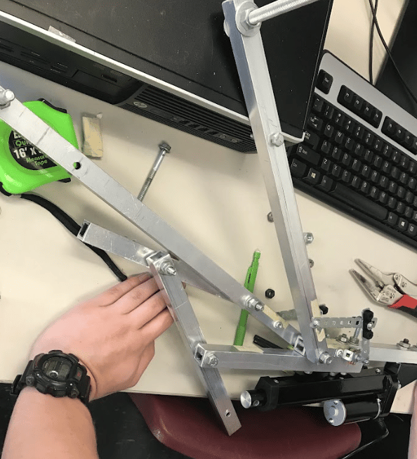

Building Process
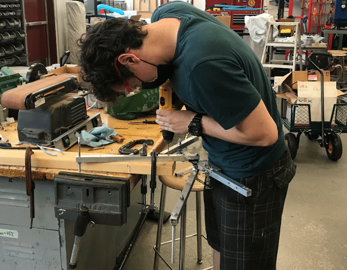

Here, Trevor is drilling holes into the drive arm to attach the linear actuator
Next we had to figure out where to put the linear actuator to achieve the angle bends we want
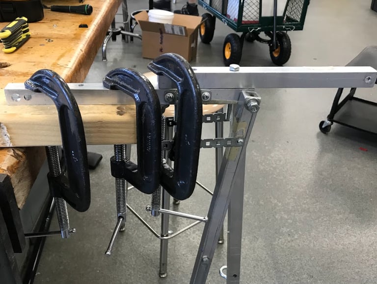

You can never have too many clamps
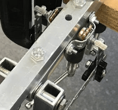

This is a close-up of the elbow joint. Notice the two potentiometers and how they pivot based on the thin metal support joints. These are just VEX robotics pieces we had lying around the workshop. The nob of the potentiometers just so happened to be the size of the square holes on the steel VEX bars. These potentiometers would be hooked up to a microcontroller on the backpack frame. They were used to know when to power the linear actuator and in what directions based on the angle of the manual arm compared to the drive arm.
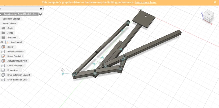
We ended up 3D modeling the arm to get a better sense of how the different parts would move. We added two more metal bars to extend the range of the linear actuator and better support the drive arm

Programming
Components
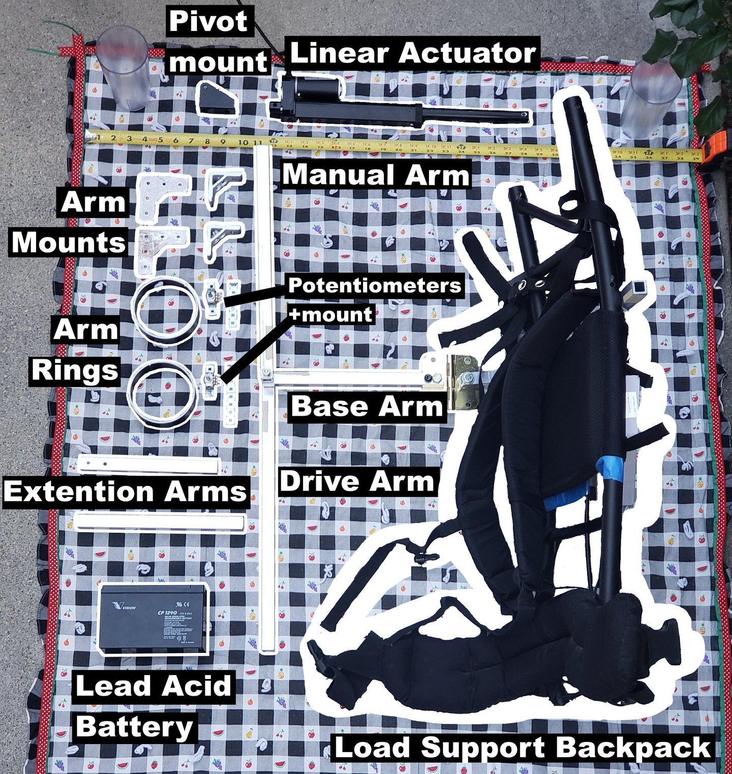

Once everything was built we hooked the linear actuator along with the potentiometers to an Arduino Uno. The linear actuator was powered by a lead acid battery. For safety reasons, this probably wasn't the best idea but it was what we had lying around that met the specifications of the linear actuator and could easily be replaced in the future.
The code was written in the Arduino IDE
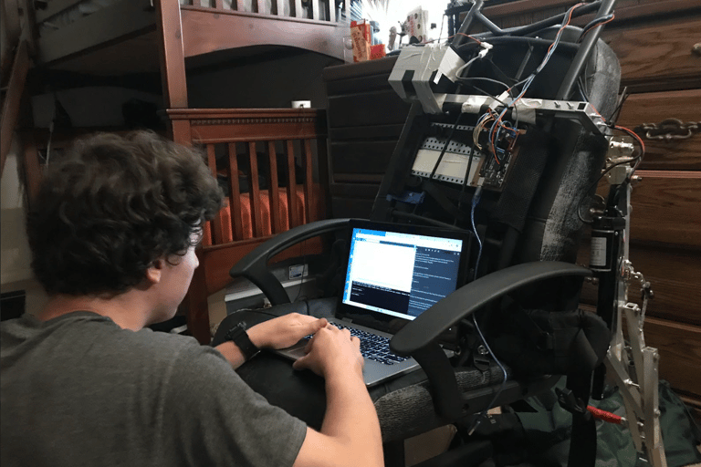

Here Trevor is programming the exo-arm in the optimal position. And yes we just duct-taped the lead acid battery on the frame. We needed a place to put it and we happened to need a counterweight on the other side as we were only building one arm, so it all worked out. Below is the GitHub repo of the code.
First Test Trials
This video is the first trial we did just powering the linear actuator by connecting it to a battery and reversing the polarity for the switching direction. This was a physical demonstration of the maximum and minimum angle the elbow joint could achieve, thus defining the bounds of the user's movement with the arm. We also used this to set values of the potentiometer for the code later on. This was also when we started to get a sense of just how slow this arm was, but at this point, it was way too late to get another linear actuator and for a proof of concept it was good enough.
First Human Test Trials
These were the first tests on a human (in this case me) before we installed the microcontroller had everything hooked up. Again, we just held wires to the battery and reversed the wires to retract the arm. In this case, the speed of the actuator is better to be slower as if it went too fast it could cause some discomfort to the user if it instantly went from extension to full curl, not to mention the shock from the jerk that it would cause to the exo-arm and user's arm.
In this test, we put about 20 Ibs of junk we found around the workshop in a plastic bag for a load-bearing test. In the video, you can see that I can curl the arm by just barely lifting the manual arm. At this point, there still wasn't a counterweight on the other side so Aleqxus was holding the left side down for stability. We would later add a counterweight albeit it was not ideal nor safe.
Load Testing with the Finished Product
Remember how I said this project was an extension of a final presentation we had to give at the end of the year? Yeah... So I will put the presentation video at the end of the post, but remember this was in high school during COVID-19 so the video is incredibly cringeworthy and corny.
But before that have some more load-bearing tests
These are both with and without the exo-arm for comparison
30Ib Load
60Ib Load
76Ib Load
Final Presentation
Cringe Warning


