Supercapacitor Power Supply
Junior design project to make a power supply for a high school-level robotic competition car.
Made a supercapacitor power supply for an autonomous vehicle.
Project Definitions
The primary goal of the project was to create a platform that high school students could easily access and learn about concepts such as how a power supply or PID controller works. As I was part of the team that built the power supply, I will focus on the hardware implementation aspect of the project.
We were tasked with designing a power supply that utilizes supercapacitors to power a small, autonomous line-following vehicle. This vehicle would then be used in a high school robotics competition hosted by the Rose-Hulman Institute of Technology to inspire students to pursue careers in electrical and computer engineering.
Features
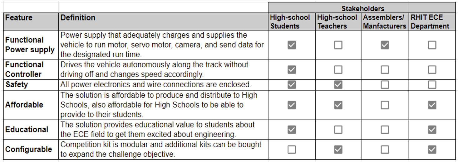
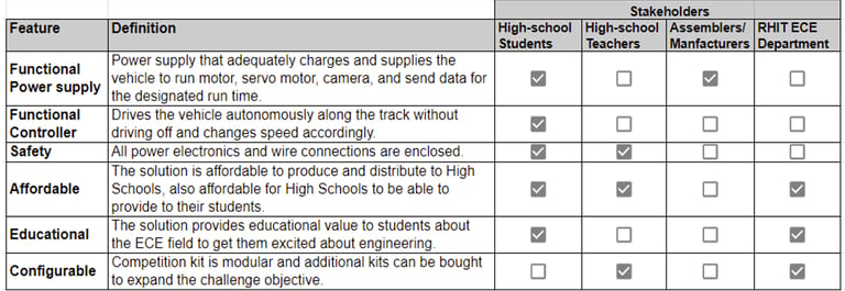
We started by defining the features our stakeholders would like to see from our design.
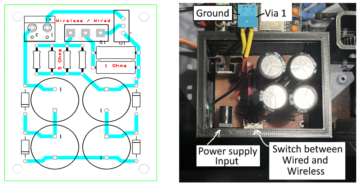
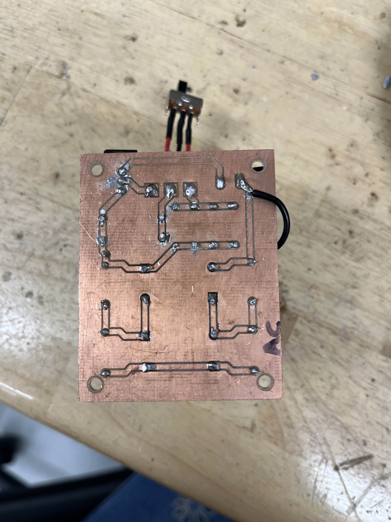
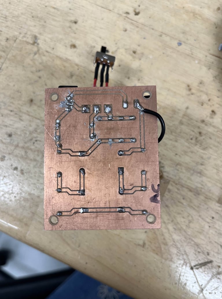
Back of PCB
Oval Track with no elevation change
Figure Eight Track with elevation change
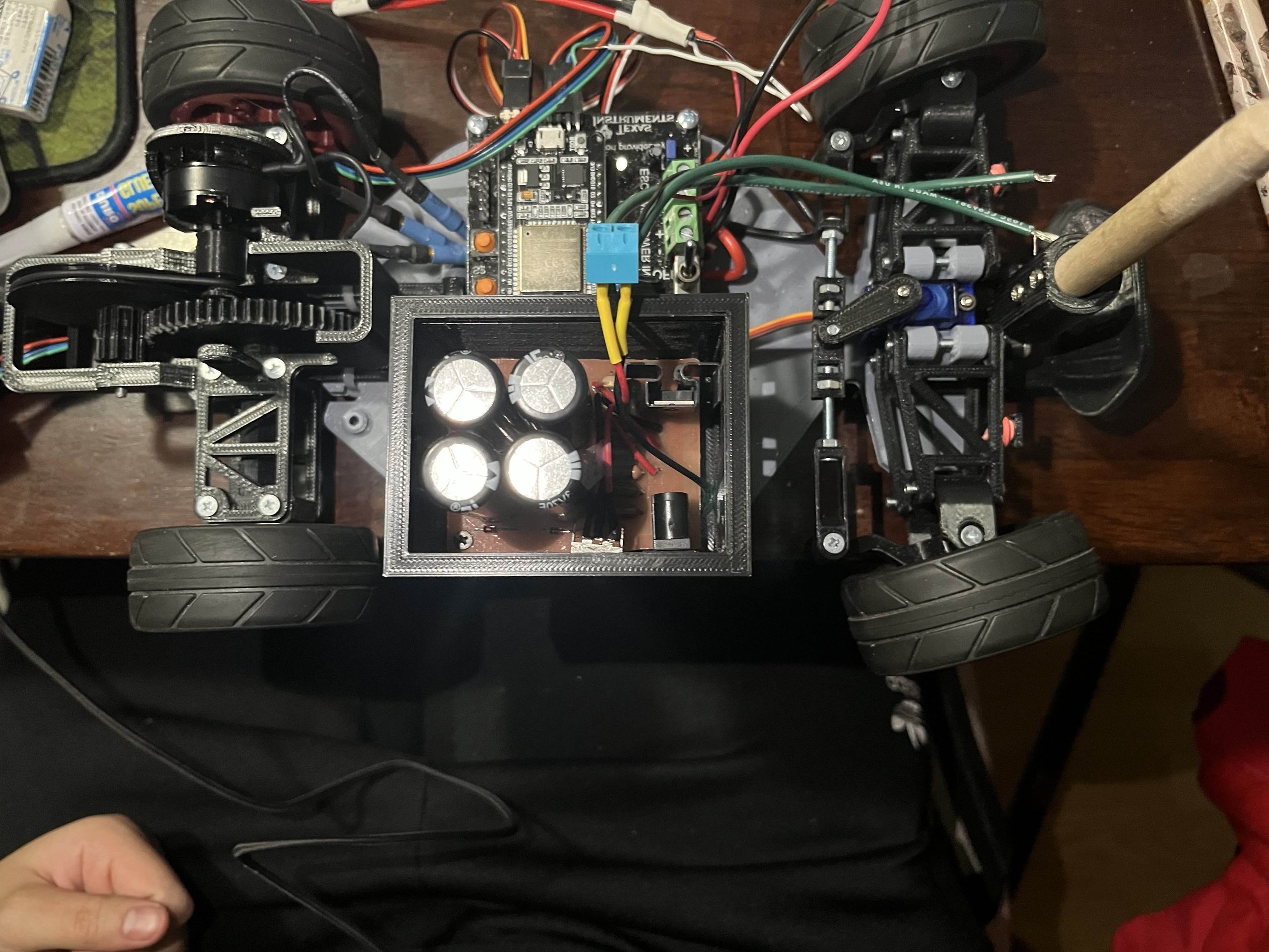
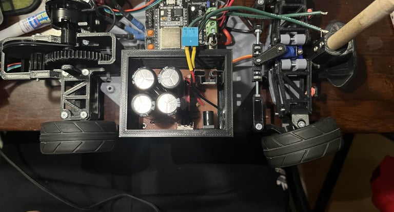
After verifying all the components were within tolerance and would meet our specifications, I soldered the components to our milled PCB. After a few continuity tests, I installed it into a 3D modeled enclosure that I also CADed up, and attached it to the autonomous vehicle. Here are a few videos of it running on the different tracks we had. You'll notice I also 3D modeled a wing to put on the back of the vehicle, just for fun.
Before I soldered all the components to the board, we tested them on a breadboard to verify that everything was in order. Here is a short video of that.
PCB Layout
The PCB was designed to be single-layer, as the PCB was to be manufactured in-house, and our department only has the capabilities for milled PCB manufacturing. A via was added for testing purposes and to hook up to the rest of the vehicle.
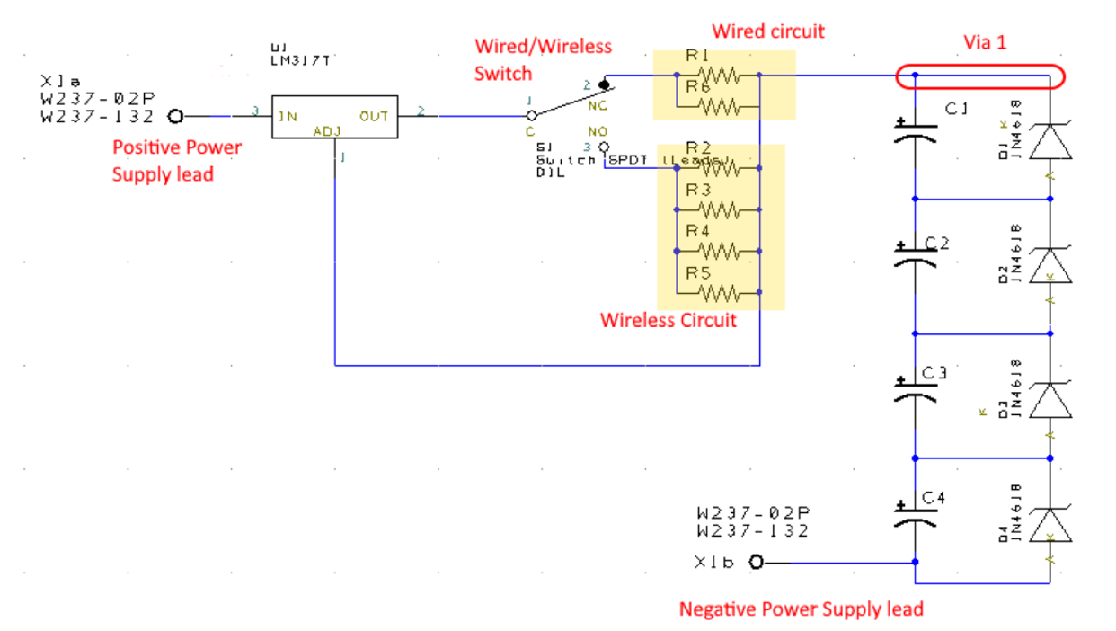
So you're probably asking why there are two circuits that hook up to the capacitors. This is because the power supply needs to have two modes, one for wired charging and the other for wireless charging. Since the input voltage and current for these two modes differ, the resistance value must change to accommodate this.
Then, after confirming the desired results with the maximum and minimum values of the components within their tolerances in Pspice (again skipping graphs, as no one will read them), it was time to create the PCB layout design.
Now, we need to actually design these circuits to the specifications we need. For the sake of readability, I'll skip the calculation details and simulations because that's boring and no one wants to see that, but look, cool schematic!
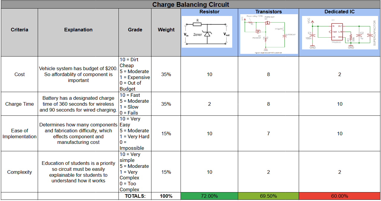
It was ultimately decided that the Resistor/Zener implementation would be best due to its low cost, ease of implementation, and ability to be understood by high school students. The only downside is that it would generally take longer to charge than the other methods; however, as long as we design it to meet the charging time requirements, this is not an issue.
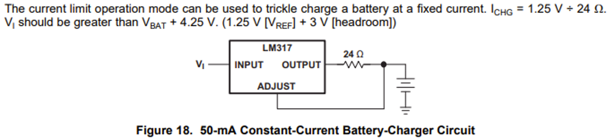
The next circuit we need is for the current limiting. The current draw for the vehicle varies depending on the torque applied to the wheel by the terrain. This means that if the motor suddenly snags something and overdraws on current, this could damage the rest of the system. A current-limiting circuit can ensure a constant, steady current at a safe amperage.
For this, a voltage regulator was chosen as it was the most straightforward implementation, and we already have them on hand in the parts room. The datasheet of this particular voltage regulator has an example relevant to our application.
Decision Matrix
Next, we needed to research how to best implement each part of the system. Supercapacitors typically come in very high capacitance (in the scale of Farads) and low voltage range (2-3 Volts) due to the limitations of the electrolytic material from which they are made. So, if we want to achieve our desired voltage output of around 12-10V, we need multiple supercapacitors in series. The issue is that if you simply hook these up in series, the caps will charge at different rates. This is a problem because the first caps will charge first and end up overvolting, causing damage to the overall power supply.
To solve this, we need to design a charge-balancing circuit to charge/discharge all the capacitors at the same rate. We started by looking into different methods of accomplishing this and weighing them against our desired criteria to pick the best one.
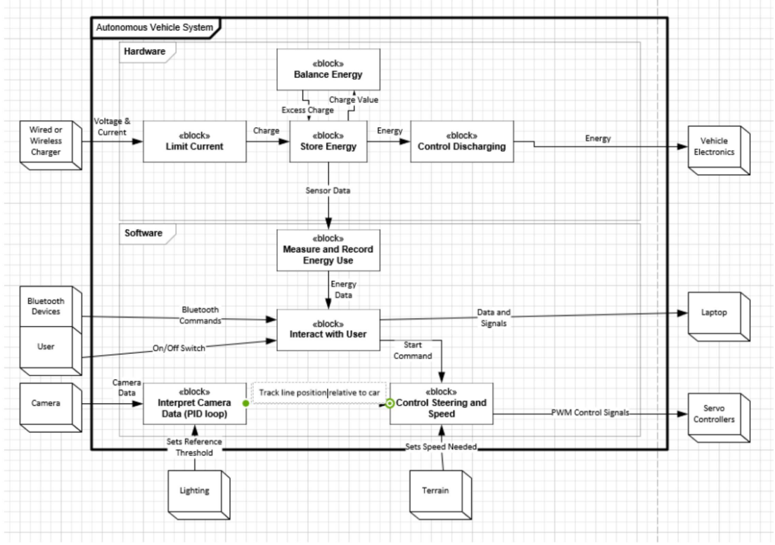
System Block Diagram
Below is our system block diagram detailing what functions each respective subsystem needs to do.
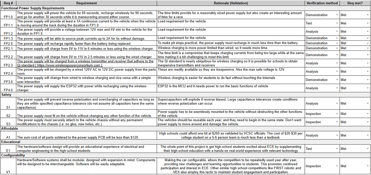
Requirements
From there, we made a requirements table to ensure the features were implemented in our final design.